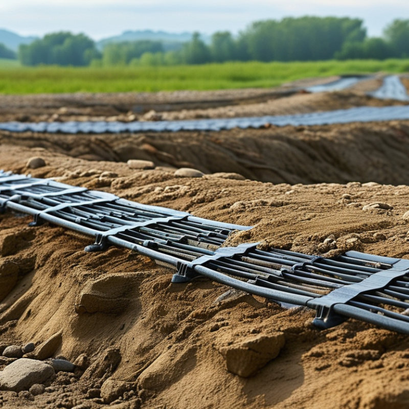
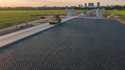
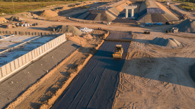
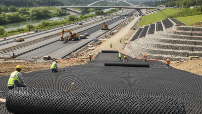
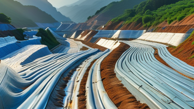
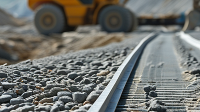
Soil stabilization often begins with a simple problem: weak ground must carry heavier loads. Rain softens the surface. Repeated traffic creates ruts. Poorly compacted fill can shift beneath a pavement layer. In these conditions, Plastic Geogrid can provide practical reinforcement and improve load distribution.
Dr. Robert M. Koerner, a respected geosynthetics educator, describes the field clearly: “Geosynthetics are synthetic materials used to improve the performance of civil engineering projects.” This principle explains why Plastic Geogrid is used beneath roads, parking areas, embankments, and working platforms. Its structured ribs interact with aggregate, helping restrain lateral movement. The result can be a more stable foundation with reduced aggregate displacement.
The benefit is not automatic.
Designers must examine soil strength, drainage, traffic loads, installation quality, and long-term exposure. A geogrid cannot correct every construction mistake. It also cannot replace proper compaction or sound drainage design. On a wet site, for example, workers may see the grid beneath angular stone while muddy water gathers around the edges. That detail matters. Performance depends on the complete system, not the product alone.
Field experience also reveals a less obvious issue: installation teams need clear instructions. Incorrect overlaps, damaged sections, or poor alignment can reduce reinforcement efficiency. Testing and project-specific calculations remain essential. This article explores why Plastic Geogrid is selected for soil stabilization, where it performs well, and where engineers should remain cautious. Practical value matters. So does honest doubt.
Plastic geogrid is a polymer grid with open, regularly shaped apertures. It is placed within soil, usually beneath aggregate layers in roads, yards, slopes, or working platforms. The grid does not act like a solid sheet. Instead, its ribs hold surrounding particles in place and create mechanical interlock.
When vehicles or stored materials apply pressure, loose aggregate tends to move sideways. Geogrid limits this lateral spreading, helping distribute loads across a wider area. This can reduce rutting, improve bearing performance, and support thinner aggregate layers when the design allows it. On weak clay or wet subgrade, the improvement may be noticeable after repeated traffic. However, geogrid cannot correct poor drainage or careless compaction. It is not a magic fix.
Tips: Match the grid strength and aperture size to the soil and aggregate. Remove sharp debris before placement. Keep the grid reasonably flat, with enough overlap at joints. Compact aggregate in controlled lifts, not all at once. Field experience also matters. A small test section can expose problems before full installation. Results may differ from calculations, especially when moisture changes quickly. Check the subgrade, drainage, and construction method together.
Plastic geogrids stabilize soil through measurable material properties, not appearance. Their open apertures allow aggregate particles to interlock with the grid. This interaction improves confinement under repeated vehicle loads. In field practice, engineers inspect junction quality, rib stiffness, and installation damage before accepting a design.
Polypropylene and high-density polyethylene are common polymers. Their low density, typically about 0.90 to 0.97 g/cm³, supports easier handling on uneven ground. Published technical data commonly report tensile strengths from roughly 20 to over 200 kN/m, depending on structure and direction. These values must be verified using ASTM D6637 testing. Ultimate strength alone can mislead. Designers should use the reduction factors required for creep, installation damage, chemical exposure, and weathering.
A useful detail is aperture stability. A grid may have impressive tensile strength but still rotate or deform during aggregate placement. FHWA guidance on geosynthetic design emphasizes interface behavior and long-term performance, while ISO 10319 measures tensile properties under controlled conditions. Field records often reveal a gap between laboratory results and construction reality. Wet subgrades, sharp stone, and poor overlap can reduce performance. The specification should state junction strength, allowable strain, rib geometry, durability evidence, and installation procedures. Some projects still rely too heavily on headline strength. That deserves reconsideration.
Why Use Plastic Geogrid for Soil Stabilization?
Plastic geogrids improve soil strength by creating mechanical interlock between their apertures and surrounding aggregate. Their ribs resist tensile movement when traffic loads press downward. This action spreads stress across a wider area. Weak subgrades then experience less rutting and surface deformation. On construction sites, the difference can appear beneath a loaded truck or beside a sharp turning area. Aggregate stays more stable, instead of pushing sideways into soft soil. The result may allow a thinner aggregate layer, but only when site conditions support that decision.
Tips: Check soil strength, drainage, and expected loads before selecting a geogrid. Keep the layer flat and remove sharp debris. Good installation matters.
Plastic geogrids also improve load distribution beneath roads, parking areas, working platforms, and temporary access routes. The grid does not replace proper compaction. It works with compacted fill to limit lateral spreading and maintain a more even platform. Correct overlap and anchoring help prevent movement during aggregate placement. Poor grading can still create weak pockets. That detail is easy to overlook.
Performance depends on aperture size, rib stiffness, soil type, moisture, and loading frequency. A solution that works on firm sandy soil may perform differently in saturated clay. Field testing and engineering calculations remain important. I have seen stabilization plans focus heavily on the product and too little on drainage. That is a mistake worth revisiting. Plastic geogrids can improve performance, but they are not a magic layer.
Representative CBR improvement and load-distribution performance in weak subgrade applications
Plastic geogrids improve soil strength through interlocking with aggregate particles, limiting lateral movement and spreading applied loads over a wider area. The representative values below show how a geogrid-reinforced aggregate layer can increase California Bearing Ratio (CBR) and reduce the stress concentration transferred to weak subgrade. Actual results depend on soil type, moisture, aggregate quality, installation, and loading conditions.
Plastic geogrid improves soil stabilization by creating tensile support within compacted fill. Its open apertures interlock with gravel, limiting lateral movement under repeated traffic loads. In road construction, this can help weak subgrades carry aggregate more efficiently. The FHWA’s Geosynthetic Design and Construction Guidelines explain that reinforcement may reduce rutting and control deformation, but results depend on soil, drainage, loading, and installation quality.
Roads are only one application. On slopes, plastic geogrid can reinforce compacted soil layers and improve resistance to shallow sliding. It is useful beside highways, around embankments, and on landscaped grades where erosion begins after heavy rain. Engineers must check slope geometry, groundwater, and pullout resistance. A stronger grid cannot correct poor drainage. That mistake happens.
Retaining structures often use geogrid layers behind facing panels or wrapped soil lifts. These layers transfer earth pressure into the reinforced soil mass. FHWA case documentation for Geosynthetic Reinforced Soil bridge systems reports construction cost reductions of about 25–60% and time savings of roughly 50–80% compared with conventional methods. Those figures are project-specific, not guaranteed. A 2022 International Geosynthetics Society technical review also emphasizes material durability, connection strength, and long-term creep testing. Field experience suggests installation is less forgiving than drawings imply. Misaligned layers, insufficient overlap, or loose backfill can quietly weaken the system.
Why Use Plastic Geogrid for Soil Stabilization?
Selecting a plastic geogrid starts with the soil, not the product label. Field testing should identify subgrade strength, drainage, moisture, and expected traffic. A stronger grid is not automatically better. Aperture size must interact with the aggregate, while junction efficiency and tensile stiffness should match the design load. FHWA guidance, NHI-07-092, reports aggregate reductions of roughly 20% to 50% in suitable reinforced applications. The result depends heavily on soil conditions and construction quality. ASTM D6637 and ISO 10319 provide useful tensile testing references.
Installation details often decide performance. Remove sharp stones and standing water before placement. Pull the grid flat, without folds or stretched sections. Overlap widths commonly range from 300 to 600 millimeters, but weak soils may require more. Place aggregate from the edge or on previously covered areas. Direct tipping onto uncovered geogrid can cause displacement. Compact in controlled lifts, and inspect the surface after the first roller pass. My field experience suggests that rushed placement creates more problems than insufficient tensile strength. That assumption deserves review on every project.
Tips: Confirm the design with a qualified geotechnical engineer. Record subgrade readings before installation. Check rolls for damage and verify certificates against the specified standards. If rutting appears during placement, stop and reassess the lift thickness, moisture, and support conditions. FHWA, Geosynthetic Design and Construction Guidelines, recommends documenting these site controls for reliable quality assurance.
| Factor or Performance Dimension | Typical Data or Requirement | Why It Matters for Soil Stabilization | Selection and Installation Guidance |
|---|---|---|---|
| Primary Material | Common plastic geogrids are manufactured from polypropylene, high-density polyethylene, or polyester-based polymers. | Polymer type affects tensile behavior, chemical resistance, stiffness, durability, and temperature performance. | Select the polymer according to soil chemistry, expected loading, installation conditions, and project design life. |
| Geogrid Function | Plastic geogrids may provide reinforcement, lateral restraint, separation support, or improved aggregate confinement. | The grid interlocks with aggregate particles and helps distribute applied loads over a wider area. | Confirm whether the project requires tensile reinforcement, base-course stabilization, subgrade improvement, or a combination of functions. |
| Tensile Strength | Commercial geogrid products are commonly available with ultimate tensile strengths ranging from approximately 20 to more than 200 kN/m, depending on product type and direction. | Higher tensile capacity can improve resistance to lateral spreading and rut development under repeated traffic loading. | Use the design tensile strength after considering installation damage, creep, durability, and required reduction factors rather than relying only on ultimate strength. |
| Tensile Direction | Uniaxial geogrids are strongest primarily in one direction; biaxial geogrids provide tensile resistance in two principal directions; triaxial products use a multi-directional structure. | Loading direction and aggregate movement determine how effectively the grid can restrain the soil or aggregate layer. | Use uniaxial reinforcement for predominantly linear applications such as slopes or walls, and biaxial or multi-directional products for paved areas and working platforms when appropriate. |
| Aperture Size | Typical aperture dimensions are often approximately 20 to 80 mm, although actual sizes vary by product and application. | Openings must allow aggregate particles to interlock with the grid without passing through excessively or becoming trapped above it. | Match the aperture size to the aggregate grading, particle size, and required mechanical interlock. Confirm compatibility with project specifications. |
| Rib and Junction Strength | Strength must be maintained through both the longitudinal and transverse ribs, as well as at their junctions. | Weak junctions can reduce load transfer and may cause localized deformation during aggregate placement or service loading. | Review manufacturer test data for junction efficiency, tensile strength, and resistance to construction-related damage. |
| Soil and Aggregate Conditions | Performance depends on subgrade strength, moisture content, gradation, angularity, and thickness of the aggregate layer. | Geogrids are most effective when the surrounding aggregate can interlock with the grid and transfer loads into the reinforced layer. | Complete a site investigation and verify the California Bearing Ratio, resilient modulus, or other project-specific soil parameters before design. |
| Chemical Resistance | Many plastic geogrids resist water, salts, acids, alkalis, and biological degradation, but resistance is polymer- and environment-dependent. | Exposure to aggressive soil or groundwater can reduce long-term performance if the selected polymer is unsuitable. | Assess pH, salinity, hydrocarbons, landfill leachate, and other contaminants. Use documented chemical-resistance data for the expected service environment. |
| Creep and Long-Term Design | Polymer geogrids can experience creep under sustained tensile loading, particularly at elevated temperatures. | Creep may reduce the available long-term tensile capacity and affect serviceability over the design life. | Use long-term allowable strength based on verified creep-reduction factors and the required design life, commonly 50 to 100 years for permanent infrastructure. |
| Temperature Exposure | Polymer stiffness and creep behavior change with temperature; black polymer products may reach higher temperatures under direct sunlight. | High temperatures can accelerate creep and reduce short-term stiffness during storage or installation. | Follow the specified installation-temperature limits and avoid prolonged exposure to direct sunlight before covering the material. |
| Subgrade Preparation | The subgrade should be cleared of sharp debris, protrusions, standing water, and unsuitable loose material before placement. | A smooth and stable foundation reduces puncture risk, wrinkles, and uneven load transfer. | Repair soft spots, control water, and achieve the specified formation level before deploying the geogrid. |
| Placement Orientation | For biaxial and multi-directional products, orientation is generally less critical; for uniaxial products, the primary strength direction must follow the design load direction. | Incorrect orientation can significantly reduce reinforcement effectiveness. | Install the strongest direction perpendicular to the expected tensile or lateral spreading force, as required by the engineered design. |
| Overlap and Connections | Typical overlaps may range from approximately 300 to 600 mm, but the required width depends on subgrade conditions, loading, and project specifications. | Proper overlaps maintain continuity and prevent gaps between adjacent rolls. | Place overlaps in the specified direction, secure them against movement, and increase overlap where weak or highly variable subgrade conditions require it. |
| Anchoring and Wrinkling | Geogrid should remain reasonably taut and in full contact with the prepared surface without folds or large wrinkles. | Folds can reduce aggregate confinement and create local stress concentrations. | Use pins, staples, sandbags, or other approved temporary restraints where needed, especially on slopes or in windy conditions. |
| Aggregate Cover Thickness | A minimum initial cover is commonly required before construction equipment travels directly over the geogrid; the design thickness often falls within approximately 150 to 300 mm or more. | Adequate cover protects the grid from puncture, abrasion, and excessive deformation during construction. | Place aggregate from the edge or from the covered area, avoid sudden dumping directly onto exposed grid, and follow the engineered cover thickness. |
| Construction Traffic | Uncontrolled turning, braking, or sharp maneuvering on uncovered geogrid can cause displacement or damage. | Construction damage may reduce tensile capacity before the reinforced layer becomes operational. | Restrict direct traffic on exposed material, use low-speed straight movements where permitted, and repair damaged sections before covering. |
| Drainage and Water Control | Geogrid is not a substitute for drainage. Water management may require edge drains, subsoil drains, filters, or appropriately graded aggregate. | Excess pore water can reduce soil strength and increase rutting or settlement. | Design drainage together with the stabilized section and prevent water from becoming trapped beneath or within the aggregate layer. |
| Quality Control | Important checks include product identification, roll condition, tensile properties, aperture geometry, overlap width, cover thickness, and visible damage. | Consistent installation helps ensure that the built system matches the assumptions used in design. | Record delivery inspections, installation locations, weather conditions, test results, repairs, and as-built measurements. |
| Typical Applications | Common applications include roadway subgrades, unpaved roads, working platforms, railway formations, parking areas, embankments, and reinforced soil structures. | Plastic geogrids can improve load distribution and reduce aggregate thickness or maintenance requirements when properly designed. | Use site-specific structural and geotechnical calculations for each application; do not select a product solely by nominal tensile strength. |
| Environmental and Service Life Considerations | Expected service life depends on polymer durability, ultraviolet exposure, temperature, chemical environment, installation damage, and sustained loading. | Long-term performance is controlled by the most demanding environmental and mechanical condition. | Specify a design life and evaluate all applicable reduction factors before approving the geogrid for permanent use. |