How to Install Geogrid for Paving Projects?
Installing geogrid beneath pavement can improve load distribution, reduce rutting, and limit deformation in weak subgrades. Yet performance depends on more than placing a mesh under aggregate. Soil strength, drainage, aggregate quality, and installation accuracy all influence the result. This guide introduces a practical approach to Geogrid Paving for driveways, access roads, parking areas, and similar projects.
Experienced contractors begin with a careful site assessment. Soft clay, loose fill, standing water, and uneven grades may require different preparation methods. A simple hand inspection helps, but professional projects should include appropriate soil testing. The design should identify the expected traffic, pavement thickness, geogrid type, overlap requirements, and drainage strategy. Product instructions matter. They are not optional details.
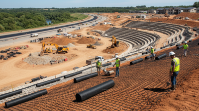
During installation, workers usually remove unsuitable soil, compact the formation, and place the geogrid flat without folds. The material should remain properly aligned while aggregate is spread carefully above it. Sharp equipment movement can shift or damage the grid. Overlaps also need attention, especially near curves, joints, and soft spots. Small mistakes become visible later.
This process is not perfectly uniform. Site conditions often challenge the original plan. A grid that performs well on firm sand may need different support over saturated clay. That uncertainty deserves honest evaluation. The following sections explain preparation, placement, anchoring, aggregate coverage, compaction, and quality checks. With measured decisions and documented inspections, geogrid can become a reliable part of a durable paving system.
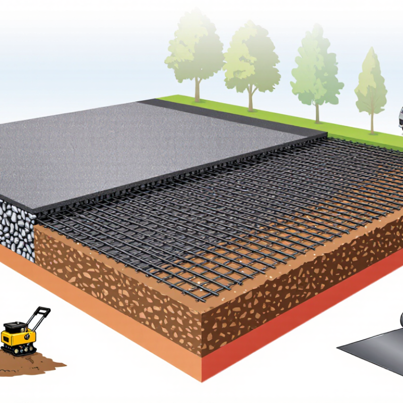
Assessing Site Conditions and Selecting the Right Geogrid
Before installing geogrid, inspect the soil beneath the proposed pavement. Record soil type, moisture, drainage, groundwater, and surface soft spots. A practical screening range treats CBR below about 3 percent as weak subgrade. Confirm this value with in-situ testing, not visual judgment alone. Dynamic cone penetration tests, plate-load tests, and proof rolling reveal different problems. FHWA-NHI-07-092 stresses that construction control and subgrade preparation strongly influence geosynthetic performance.
Look closely at traffic and aggregate conditions. Estimate heavy-vehicle loading, seasonal moisture, and expected service life. Then select geogrid by tensile strength, junction efficiency, aperture size, and installation survivability. A stiff junction can improve aggregate confinement, while an unsuitable aperture may provide little interlock. The U.S. Federal Highway Administration’s LTPP database contains performance data from more than 2,500 pavement sections. Its records show how moisture, drainage, and variable subgrades affect pavement distress over time. That evidence supports treating drainage as part of geogrid design, not an afterthought.
Do not specify geogrid from tensile strength alone. I have seen clean-looking sites fail after rainfall exposed pumping beneath the base. Remove or stabilize unstable soil, compact the foundation, and prevent wrinkles during placement. AASHTO guidance and FHWA construction recommendations both support documented material testing, overlap control, and careful aggregate placement. Product data should include test methods, not only attractive headline values. Field conditions often change. The design may need a second review.
| Assessment or Selection Dimension | Typical Site Information or Field Indicator | Recommended Action | Installation and Quality-Control Check |
|---|---|---|---|
| Existing Soil Type |
|
Use geogrid primarily for aggregate confinement and lateral restraint. On weak or fine-grained subgrades, consider a geotextile separator or a geocomposite system in addition to geogrid when specified by the design. | Confirm the soil classification through visual inspection, sampling, and laboratory testing where required. Remove unsuitable organic material before placing the pavement foundation. |
| Subgrade Strength | Common indicators include field proof-rolling results, California Bearing Ratio (CBR), resilient modulus, or measured deflection. A soft area may rut, pump, or deflect under construction traffic. | Do not select geogrid by tensile strength alone. Use the pavement design to determine whether reinforcement, stabilization, thicker aggregate, undercutting, or improved drainage is needed. | Proof-roll the prepared subgrade with suitable equipment. Mark yielding areas, correct them, and retest before aggregate placement. |
| Moisture and Drainage | Standing water, seepage, a high water table, or seasonal saturation can reduce subgrade support and cause pumping or rutting. | Provide positive surface drainage and, where appropriate, edge drains, underdrains, or a drainage layer. Geogrid does not replace drainage or soil improvement. | Keep the subgrade firm and free of standing water. Prevent construction traffic from disturbing saturated soil. |
| Traffic and Loading | Consider construction traffic, passenger vehicles, delivery trucks, buses, forklifts, and the expected number of load repetitions. | Use the pavement thickness design and anticipated loading to establish the required aggregate base thickness and reinforcement function. Heavy or repetitive loading generally requires more rigorous design verification. | Confirm that the installed aggregate thickness and compaction meet the project specification before allowing regular traffic. |
| Geogrid Function | Geogrid may be used for aggregate interlock, base-course confinement, tensile reinforcement, or reduction of aggregate spreading. | Select a product whose aperture geometry, junction performance, stiffness, and durability suit the intended function. A product designed only for separation should not automatically be treated as reinforcement. | Verify the product type, roll identification, installation instructions, and project-specific approval before use. |
| Geogrid Material Type | Common geogrid materials include polypropylene, polyester, and high-density polyethylene. They differ in stiffness, creep behavior, chemical resistance, and installation characteristics. | Match the polymer and coating to the expected temperature range, soil chemistry, ultraviolet exposure during storage, and long-term design requirements. | Store rolls on a stable surface, protected from prolonged ultraviolet exposure, puncture, mud, and standing water. |
| Aperture Size and Aggregate Compatibility | The aggregate should be able to partially penetrate or interlock with the apertures without passing excessively through them. | Select aperture dimensions compatible with the nominal aggregate size. The grid should provide effective confinement rather than acting as a smooth layer between soil and aggregate. | Check the aggregate gradation and visually confirm that the grid remains well seated as the initial aggregate lift is placed. |
| Tensile Strength and Stiffness | Tensile strength is commonly reported in kilonewtons per metre (kN/m), but performance also depends on strain, junction strength, rib stiffness, and installation damage resistance. | Compare products using the same test method and design strain. Use project calculations or a qualified pavement engineer's recommendation rather than choosing solely by the highest nominal strength. | Review certified test data and ensure the specified design properties are not confused with ultimate laboratory values. |
| Subgrade Preparation | The surface should be shaped to the required line and grade, compacted where practical, and free from sharp rocks, debris, deep ruts, and abrupt depressions. | Repair soft spots and fill local depressions before placing the geogrid. Avoid installing over unstable material that may deform during aggregate placement. | Inspect the surface immediately before deployment. Do not place geogrid on frozen, flooded, or excessively muddy subgrade unless the approved method specifically permits it. |
| Placement and Alignment | Geogrid is generally placed directly on the prepared subgrade or at the design elevation within the aggregate layer. | Unroll the grid in the specified direction, keep it reasonably taut and free of folds, and provide the specified overlaps at seams and edges. | Minimize wrinkles and secure the grid with pins or staples where needed. Follow the project specification for transverse and longitudinal overlap; common practice often uses approximately 300–600 mm, but the design requirement governs. |
| Aggregate Placement | Direct construction traffic on uncovered geogrid can cause displacement or damage, especially over weak subgrade. | Place aggregate by end-dumping or controlled spreading where appropriate. Establish an initial cover layer before allowing repeated equipment passes. | Avoid sudden braking, sharp turning, and tracked equipment directly on exposed grid. Repair damaged sections before covering. |
| Aggregate Thickness Above Geogrid | Required thickness depends on subgrade strength, traffic, aggregate quality, drainage, and the pavement design. | Use the engineered section rather than a universal thickness. Weak subgrades and heavy construction traffic may require a thicker initial lift to protect the installation. | Measure aggregate thickness at multiple locations and verify that the finished layer meets the design elevation and compaction requirements. |
| Compaction | Proper compaction creates aggregate interlock and provides a stable working platform for the paving layers. | Compact the aggregate using equipment suitable for the material and site conditions. Avoid overworking wet or unstable areas. | Verify density or stiffness using the test method specified for the project. Correct rutting, segregation, and soft areas before paving. |
| Environmental Exposure and Durability | The installation may be exposed to moisture, freeze-thaw cycles, hydrocarbons, alkaline materials, or ultraviolet radiation during construction. | Select a geogrid with documented resistance appropriate for the expected chemical, biological, thermal, and ultraviolet conditions. | Cover the grid within the recommended exposure period and prevent contamination by fuel, oils, solvents, or construction waste. |
| Final Acceptance Criteria | The completed foundation should be uniform, properly graded, adequately compacted, and free of visible instability. | Approve the layer only after confirming the geogrid installation, aggregate thickness, drainage provisions, and test results comply with the project requirements. | Record inspection locations, roll identification, overlap measurements, repairs, material quantities, compaction results, and photographs before the pavement surface is placed. |
Note: Final geogrid type, placement elevation, overlap, aggregate thickness, and pavement structure should be established by the project specifications and a qualified pavement or geotechnical professional.
Related Posts
-
What Is the Best Gravel Geogrid from China?
-
Best Cirtex Geogrid Solutions for Global Buyers?
-
2026 Best Geogrid Fabric Options for Your Construction Projects?
-
Why Choose Geogrid Fabric for Your Construction Projects?
-
2026 Best Plastic Geogrid Solutions for Global Buyers?
-
2026 Best Gravel Geogrid Solutions for Global Buyers?
-

Phone
-

E-mail
-

Whatsapp
-

Top