10 Tips for Geotextile Uses and Selection
Geotextiles are easy to overlook beneath a road, behind a retaining wall, or along a drainage trench. Yet the right fabric can help separate soil layers, filter water, reinforce weak ground, or limit erosion. Geotextile Use depends on the project, not simply on choosing the strongest-looking roll. A woven fabric may suit one application, while a nonwoven material may perform better in another. Small details matter.
This guide, “10 Tips for Geotextile Uses and Selection,” explains how to match material properties to site conditions. It looks at soil type, water flow, strength, installation, and expected exposure. A fabric that works well under a gravel path may not be suitable for a steep slope or a saturated area. There is no universal choice. Check product specifications, test data, and the project design before purchasing, and consult a qualified professional when conditions are uncertain.
Installation deserves equal attention. Overlaps, seams, surface preparation, and protection from damage can affect how a geotextile performs. Even a suitable product can disappoint if stones tear it during placement or water cannot drain as intended. That is easy to underestimate. The tips ahead offer practical questions to ask and common selection errors to avoid. Still, every site has its own constraints, and a checklist cannot replace careful assessment. Begin with the ground in front of you.
Classify Geotextiles by Function Using ASTM D4439 Terminology
ASTM D4439 terminology helps match a geotextile to its job, rather than choosing by fabric weight alone. Common functions include separation, filtration, drainage, reinforcement, and protection. FHWA’s Geosynthetic Design and Construction Guidelines (NHI-07-092) discusses these functions and emphasizes that design depends on site conditions and material properties. Tip: Name the function before comparing products. A road subgrade may need separation to keep aggregate from mixing with soft soil; a retaining structure may need reinforcement instead.
Check the relevant test data for the intended function. For filtration, review apparent opening size and water-flow performance alongside the soil’s particle-size distribution. For drainage, assess flow capacity under expected compression, not just in an unloaded test. ASTM D4491 measures permittivity, while ASTM D4751 measures apparent opening size. These values are not interchangeable, and a single number cannot predict field performance. Small detail. A clogged fabric can undermine the whole system.
Tip: Match the test to the failure risk. FHWA guidance calls for considering installation damage, clogging, and long-term durability during selection. Yet field conditions rarely match a neat laboratory specimen exactly. Document the soil, loads, drainage path, and installation method, then verify the design with qualified engineering review.
Geotextile Functions: ASTM D4439 Terminology
ASTM D4439 terminology classifies geotextiles by function. This chart inventories five commonly cited functions; equal bar lengths indicate one category each, not performance or market prevalence.
Separation: prevents adjacent materials from mixing.
Filtration: allows water through while retaining soil.
Drainage: conveys water within the geotextile plane.
Reinforcement: contributes tensile resistance to a soil system.
Containment: helps confine materials.
Set AOS Targets of 0.075–0.30 mm for Soil Filtration Design
For soil filtration, an apparent opening size (AOS) target of 0.075–0.30 mm can narrow product choices, but it is not a universal design rule. FHWA’s Geosynthetic Design and Construction Guidelines (NHI-07-092) evaluates geotextile retention against soil gradation, including D85, the particle size at which 85% of the soil is finer. AOS should therefore be checked against a representative soil sieve analysis, not selected from a general range alone. ASTM D4751 provides the test method for measuring AOS. That distinction matters: a fabric that retains fines well may still clog or restrict water flow.
Tip: Set the range as a screening target, then compare the tested AOS with the project soil’s D85 and uniformity. For a drainage trench, collect soil from the actual excavation zone; a handful from the surface may not represent deeper layers. Also check permeability and clogging resistance under expected flow conditions. The FHWA guidance treats retention and hydraulic performance as linked design checks, not interchangeable properties. Keep the soil test and product test reports with the design record.
Field conditions can complicate the numbers. Compaction, soil variation, and installation damage may alter performance, and a clean laboratory sample cannot capture every site detail. I would review the gradation with the geotechnical designer before fixing the specification. A target near 0.075 mm may suit finer soils, while coarser soils may need a different opening size; confirm both cases with tested soil data and the applicable design criteria.
Specify Tensile Strength of 10–50 kN/m for Reinforcement Applications
10 Tips for Geotextile Uses and Selection
Specify Tensile Strength of 10–50 kN/m for Reinforcement Applications
Reinforcement geotextiles help distribute loads across weak or variable soils. A tensile strength range of 10–50 kN/m suits many roads, working platforms, embankments, and temporary access routes. The correct value depends on fill thickness, traffic, subgrade strength, and expected deformation.
Do not select strength from a product table alone. Check machine-direction and cross-machine-direction values separately. Confirm results from recognized tensile testing, such as ISO 10319. A 20 kN/m fabric may work beneath a lightly trafficked gravel road, while a heavily loaded embankment may require 40 kN/m or more.
Installation damage matters.
Sharp aggregate can puncture the fabric during placement. Poor overlaps can also reduce reinforcement performance. Specify minimum overlap widths, seam requirements, and protection against construction damage. Consider creep, weather exposure, clogging, and long-term chemical contact before approving the design.
In practice, engineers should calculate a design strength after applying reduction factors for installation, creep, and durability. This value can be much lower than the advertised ultimate strength. A common mistake is treating tensile strength as the only selection criterion. I would also review rut depth, subgrade failure mode, drainage conditions, and construction equipment. Field observations often reveal that a stronger geotextile cannot correct poor compaction or inadequate drainage. The specification may need revision after trial placement and inspection.
Check Permittivity of 0.1–1.0 s⁻¹ and Hydraulic Conductivity ≥10⁻⁴ m/s
A geotextile’s permittivity, measured in s⁻¹, indicates how readily water crosses its plane. A target of 0.1–1.0 s⁻¹ can help screen candidates, but it is not a universal design rule. The FHWA’s Geosynthetic Design and Construction Guidelines (NHI-07-092) stresses matching geotextile properties to the soil and drainage conditions. Test permittivity using ASTM D4491, and check that the test condition reflects the product specification. Small differences matter.
Hydraulic conductivity of at least 10⁻⁴ m/s is a useful screening threshold for some drainage applications. Yet the surrounding soil can control system performance. Fine silt may clog openings; a clean, coarse drainage layer behaves differently. Check the soil gradation, expected flow, and risk of long-term clogging before selecting the fabric. Field experience can expose issues that a neat laboratory number misses. It happens.
Ask for test reports showing permittivity and conductivity, not just a product summary. Compare values measured under consistent methods, then consider loading and installation damage. FHWA guidance also treats filtration and drainage as connected design functions. A fabric that passes water quickly but retains soil poorly may create problems downstream. I would recheck the design assumptions after a site visit; drawings do not always capture wet spots or variable fill.
Control Installation with 0.3–1.0 m Overlaps and ASTM Quality Tests
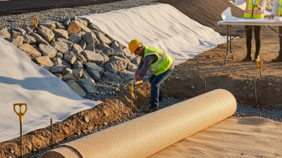
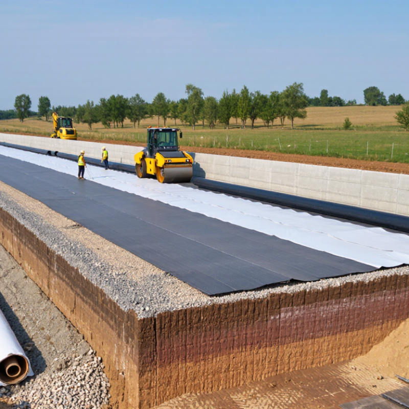
A geotextile seam can become the weak point long before the fabric itself fails. Set overlap width from the design and ground conditions: 0.3 m may suit firm, even subgrades, while soft or irregular ground can require widths approaching 1.0 m. FHWA’s Geosynthetics Engineering Manual (NHI-07-092, 2008) discusses overlap selection in relation to subgrade support and installation conditions. Treat that range as a field check, not a universal rule. A muddy rut can swallow a neat-looking seam.
Before placement, confirm roll direction, seam location, and overlap in the project specification. Mark the required width on the fabric with chalk, then check it again after machinery passes. ASTM D4354 covers sampling geosynthetics for testing; ASTM D4759 addresses establishing conformance to specifications. For measured properties, ASTM D4491 tests water permeability, D4632 grab tensile strength, and D4833 puncture resistance. These tests answer different questions. A passing tensile result does not prove adequate permeability.
Keep certificates and lot numbers with site records, and compare test results against the specified values and test methods. FHWA guidance emphasizes matching geosynthetic properties to intended function and site conditions. If a roll is damaged, or overlap narrows at a corner, stop and document the repair before covering it. I would not rely on a single spot measurement. Check several seams, especially where the subgrade changes; rushed inspections miss the awkward places.